Tray dryers
Practical Action
in order to maximise output 24 hour working is recommended
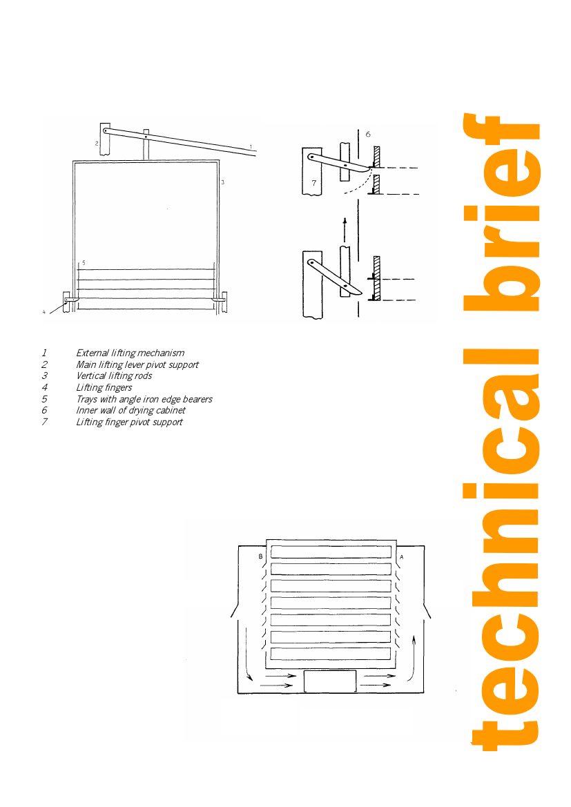
Typical semi-continuous dryers are shown in Figure 3, which shows the lifting mechanism and the
gap above the lowest tray that is ready for removal.
Detail of lifting fingers
1 External lifting mechanism
2 Main lifting lever pivot support
3 Vertical lifting rods
4 Lifting fingers
5 Trays with angle iron edge bearers
6 Inner wall of drying cabinet
7 Lifting finger pivot support
Figure 3: Semi-continuous dryers
Cross flow chambers. Although Practical Action has not developed this system it is considered worth
mentioning in this short brief. In this chamber the air is blown, through a series of louvers, directly
across the trays and then re-circulated over the heater. In the early stages of drying, when a lot of
water is being removed, a high proportion of the air is vented to an exit and replaced by fresh air. As
drying proceeds the proportion of vented air is reduced. At the end of the drying cycle no air is
vented. This system then
overcomes the problems
associated with batch and
semi-continuous cabinets in
Product trays
that:
labour costs are low as it
works like a batch dryer
all the trays dry at the same
Wet air
exhaust vent
Dry air
inlet
rate
fuel efficiency is
maximised.
Cross flow systems are
however, technically more
complex and require automatic
humidity sensors to control the
percentage of air vented during
the drying cycle.
Heating fan
A – Inlet Vent
B – Exhaust Vents
Opening/Closing controlled by
humidistat
Figure 4: Schematic diagram of a cross flow cabinet
3